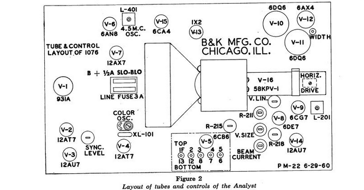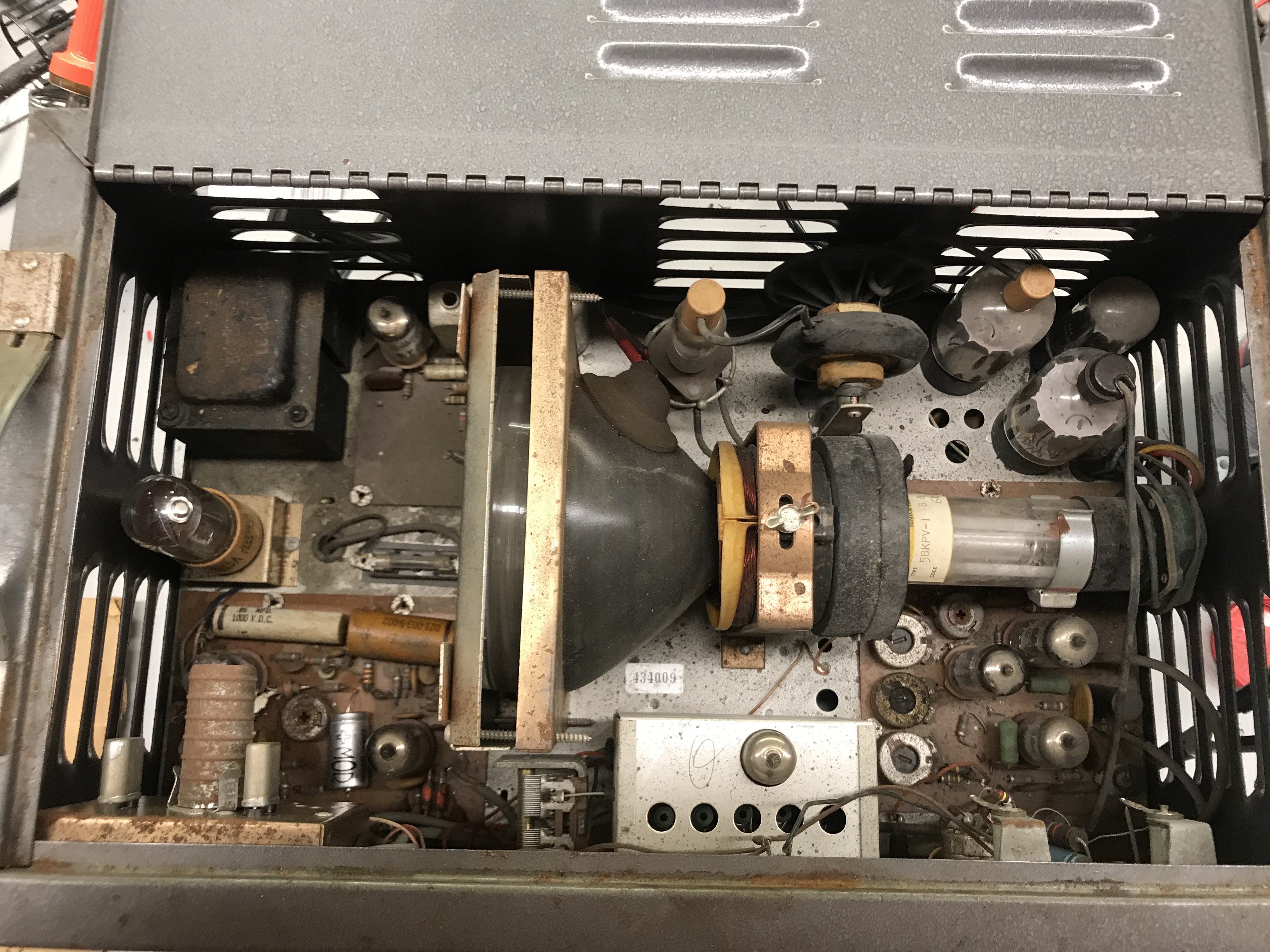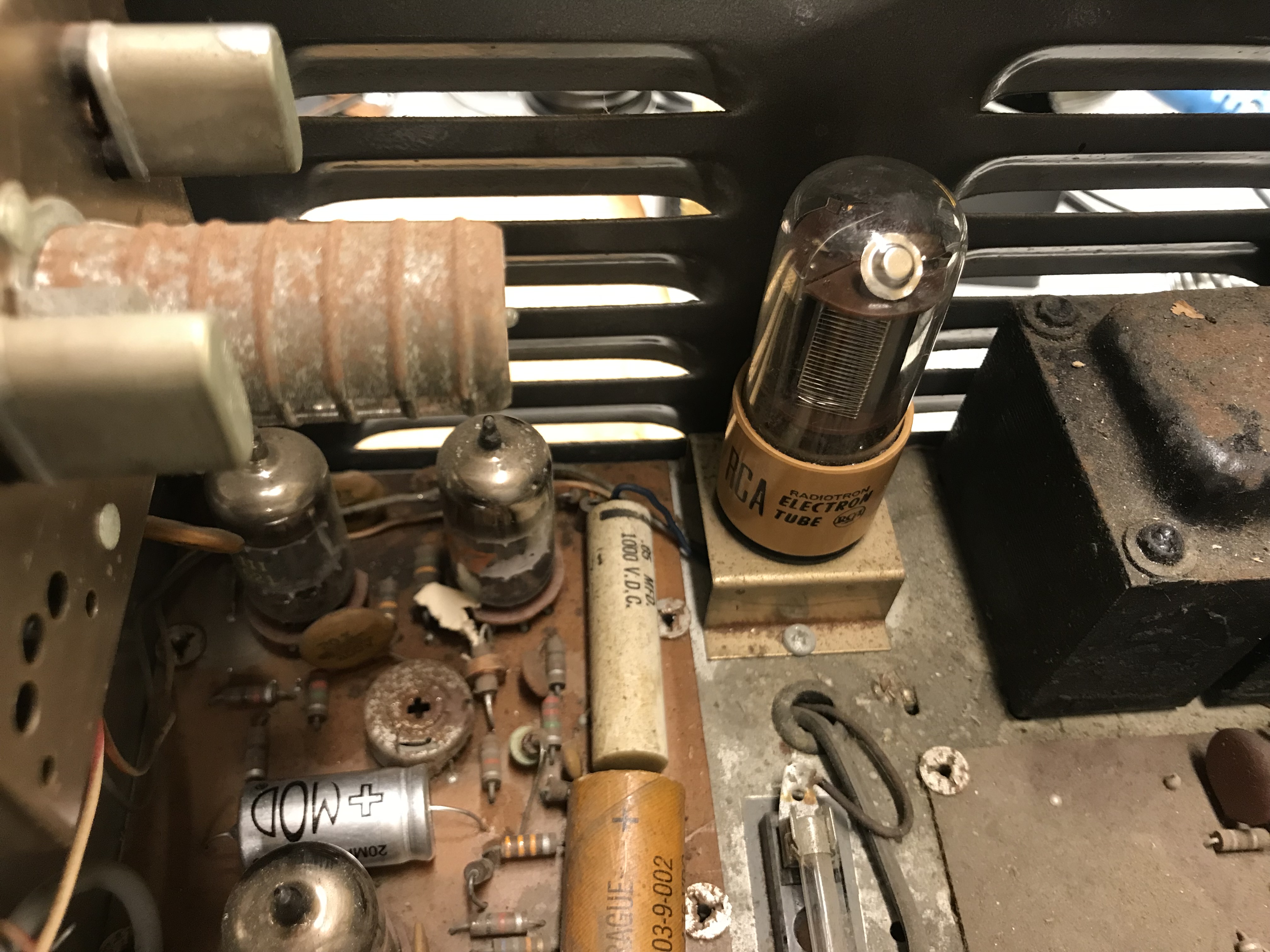
To generate the video signal a "Flying Spot Scanner" (FSS) is used. The main flying spot scanner circuit relies on several tubes, the two most interesting of which are the 5BKPV-1 and 931A tubes. The 931A is a mass market cold cathode photomultiplier tube. The 5BKPV-1 tube is a special use CRT without video modulation on the gun.
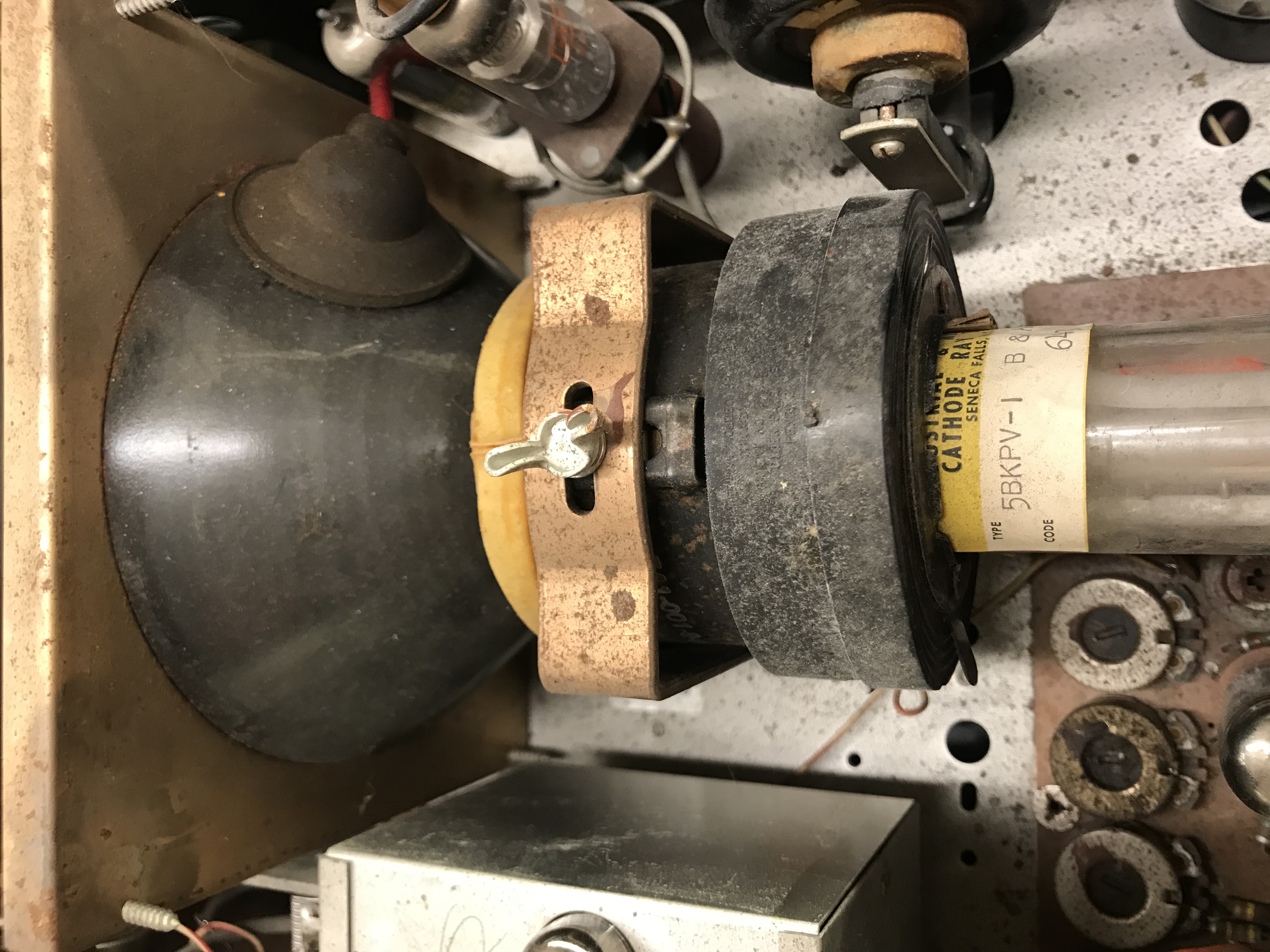
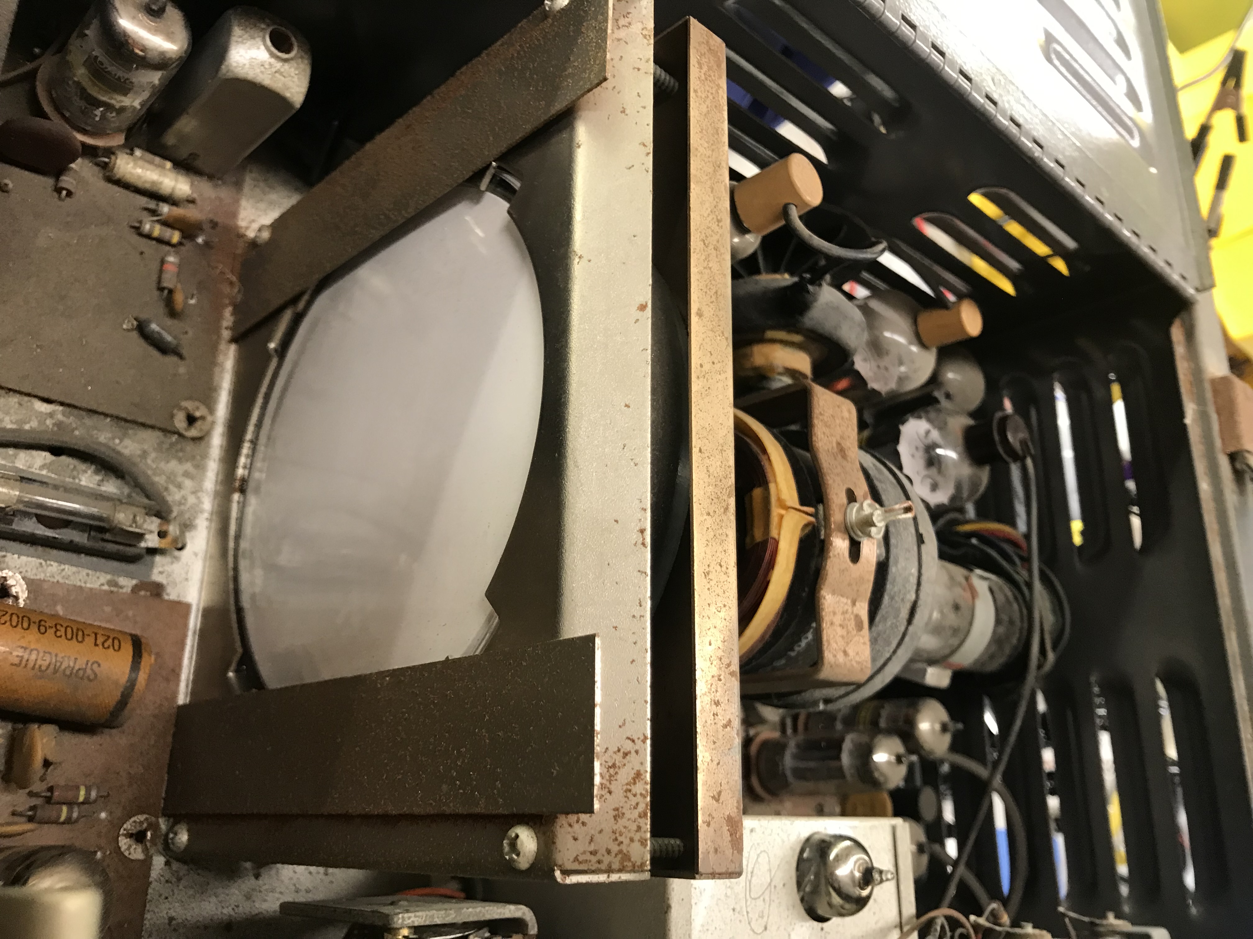
Additionally, the CRT is coated with a vilot phosphor which also emits some UV light. This is done to match the spectral response of the photomultiplier tube.
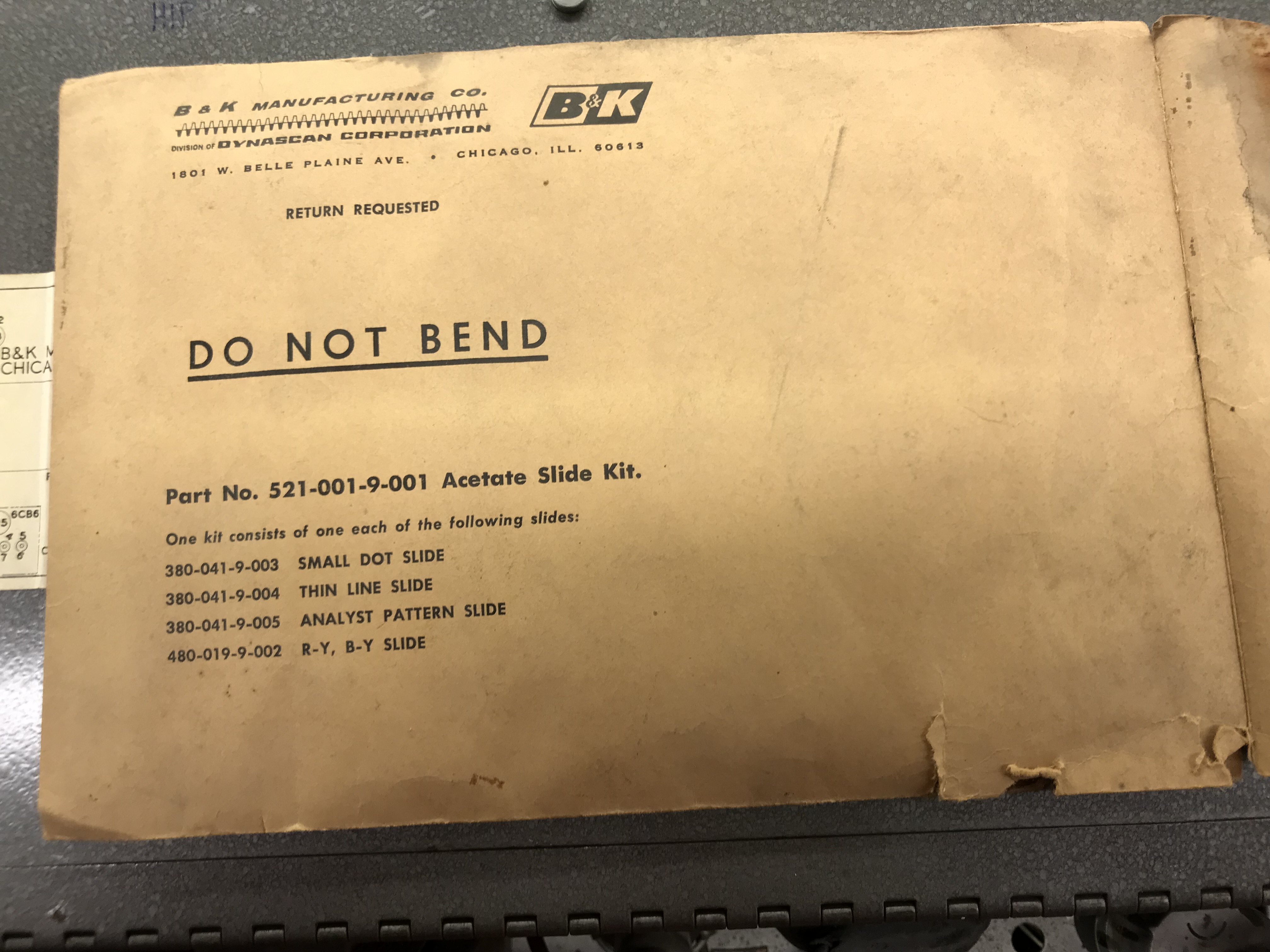
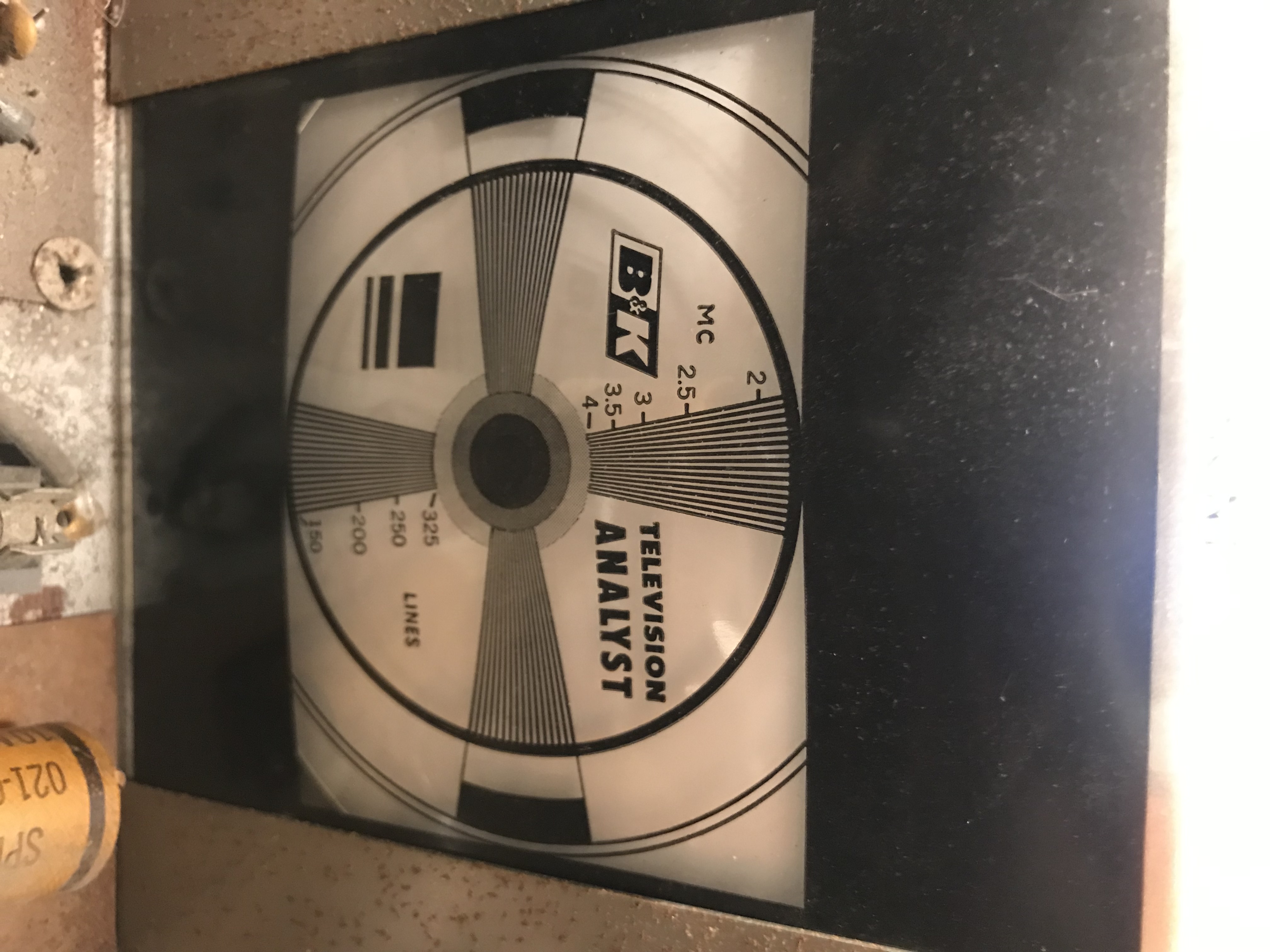
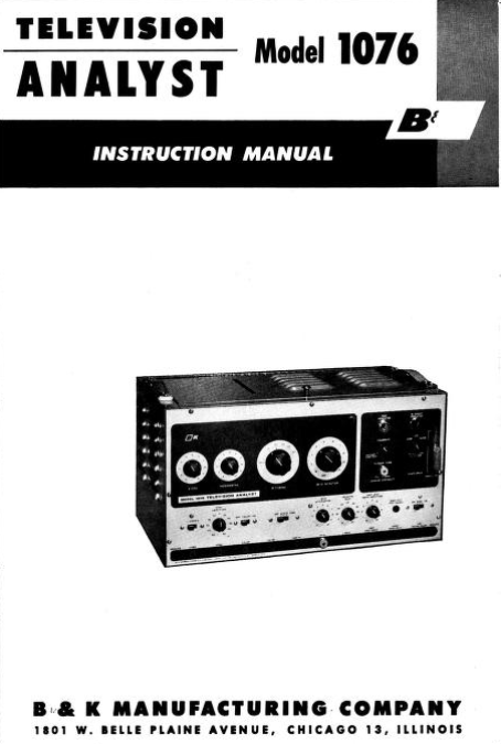
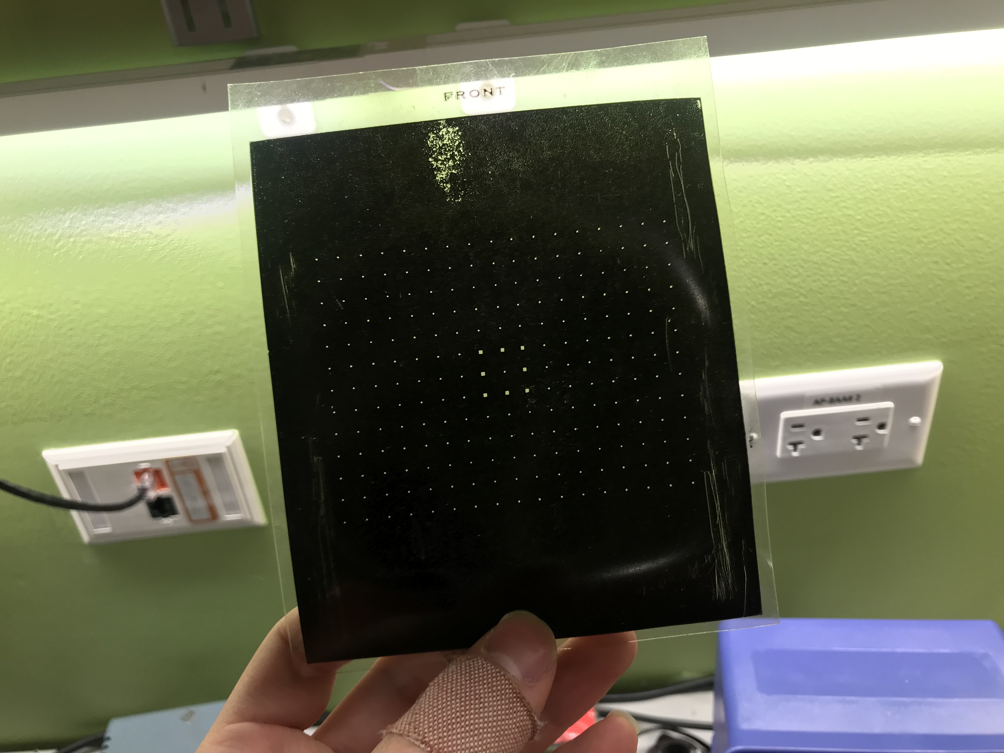
My analyst came with the original manual and test patterns! The test cards are intended to slip in front of the 5BKPV-1 Tube. There appears to be some damage around the edges of some cards however it isn't significant enough to interfere with the composite video signal.
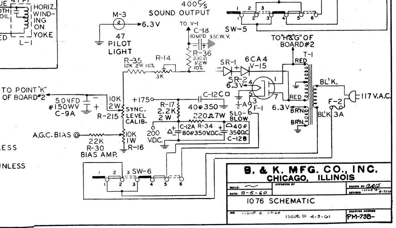
The power supply in this unit is conventional. It consists of a power transformer, a low-voltage rectifier (6CA4), and an RC filtering circuit for the B+ voltage. The power supply is also fitted with a "Standby" mode. In this state, only the tube filaments receive power. This way, it is A: safer to change slides without turning off the set, and B: reduces the likelihood of thermally damaging the tubes.
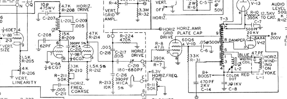
The horizontal deflection of the 5BKPV-1 resembles that of a domestic television set. It uses a free-running 6CG7 multivibrator which drives a 6DQ6 output tube. The deflection frequency can be adjusted by adjusting R11. L-201 pulls the 6CG7 towards its resonant frequency (15,750 CPS for 525 line sets).
The vertical deflection circuit is much more interesting because it has no vertical oscillators! The vertical deflection system consists of a neon lamp NE-2L and a 6RE7 twin triode. The vertical signal is derived from a high voltage winding within the power transformer secondary. The neon lamp clips the 60-cycle sine wave from the transformer secondary and uses it to drive one side of the 6RE7. Since the vertical oscillator is tapped directly from the AC line, no vertical hold control is required.
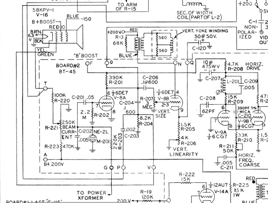
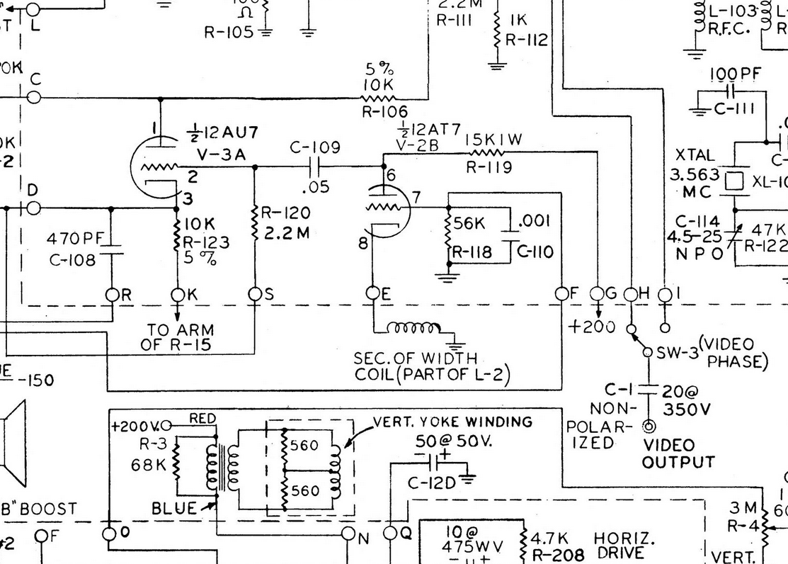
The set contains two 6DQ6 tubes, one to drive the flying spot scanner, and the other to provide horizontal plate drive substitution signals. The synch pulses are generated by mixing horizontal and vertical signals in V-2B. The signal mixing occurs in the plate circuit of the V-2B (12AT7). After, the mixed synch pulses are capacitively coupled to the grid of V-3A, which is the synch amplifier/clipper.
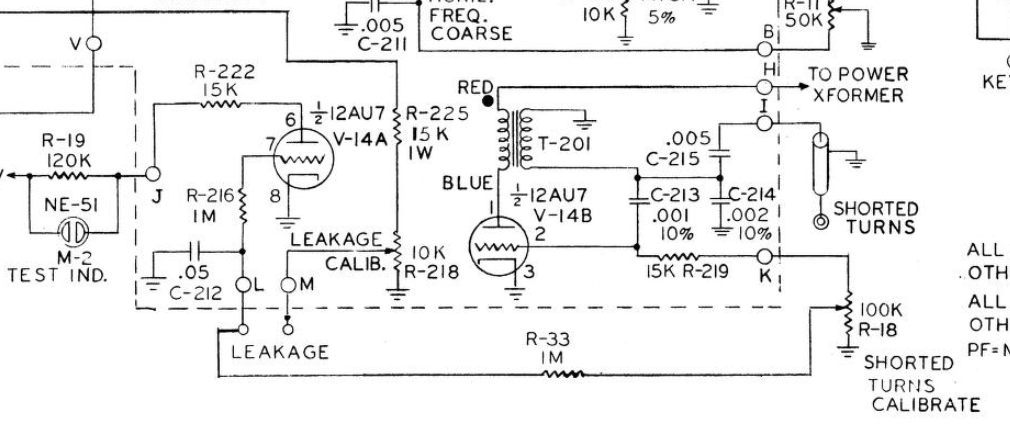
The analyst also had a yoke test built in! The test is based around a pulse oscillator which is sensitive to inductance and "quality factor" or "Q". The bias of V-14 A (DC amplifier) is dependent on the "Q" value. This means a reduction in "Q" alters the bias of the DC amplifier, causing it to conduct. The amplifier is connected in series to a neon bulb. When the neon bulb illuminates, a shorted condition is concluded. This test is sensitive, as little as one shorted turn is enough to set off the neon light.
UPDATE 6/11/24
ITS ALIVE!!!!

ITS ALIVE! I powered up the analyst on a variac and isolation transformer. The analyst sat for an hour at 115 volts to reform the leaky capacitors I didn't feel like replacing. I confirmed the presence of high voltage by placing a miniature neon bulb near the high-voltage rectifier tube. The flyback transformer carries powerful electric currents that induce large magnetic fields. The magnetic field excites neon vapor inside the bulb, so when the neon bulb is near a wire carrying high-voltage it illuminates! I prefer using this method as it is safe and isolated.
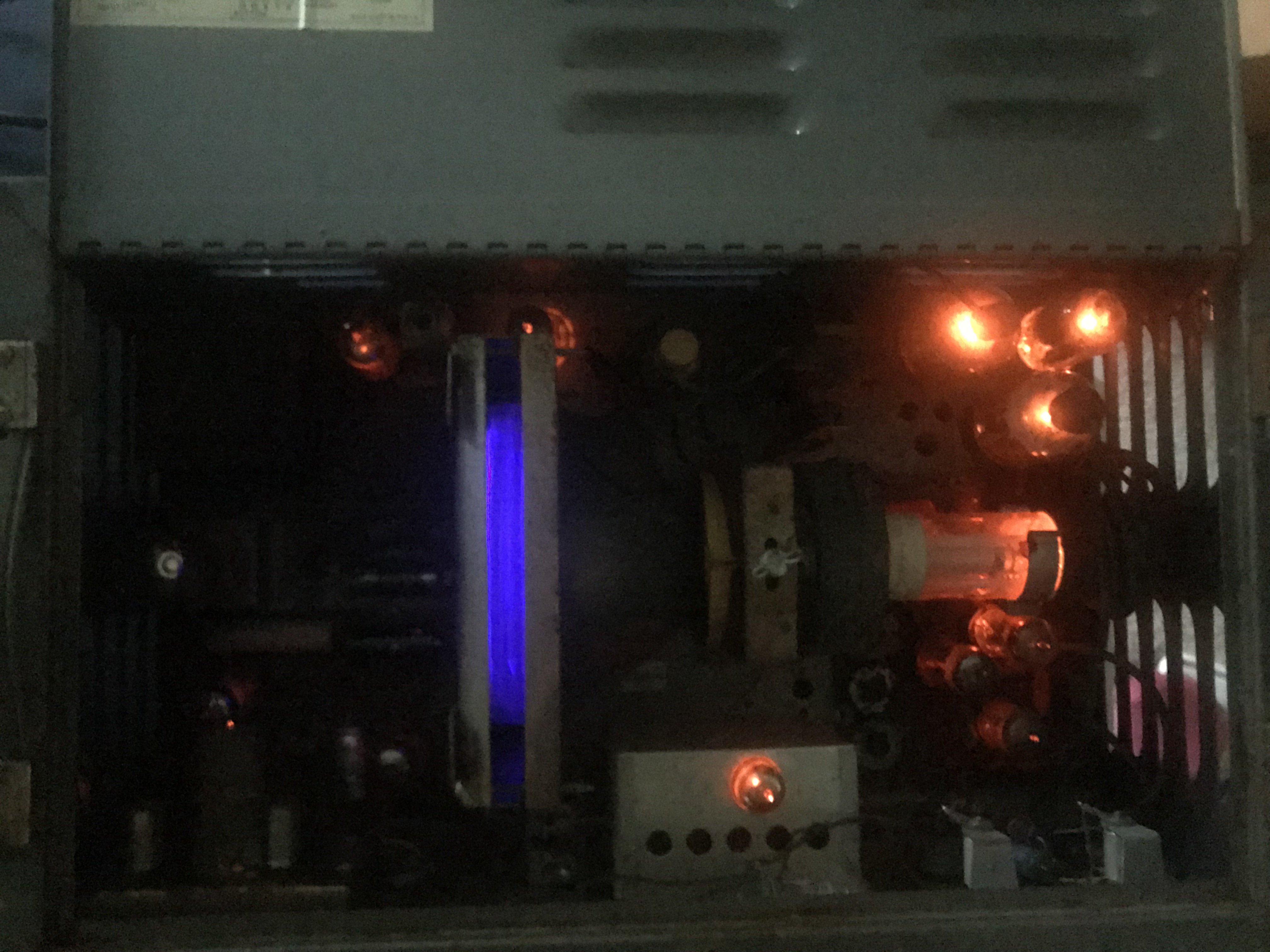
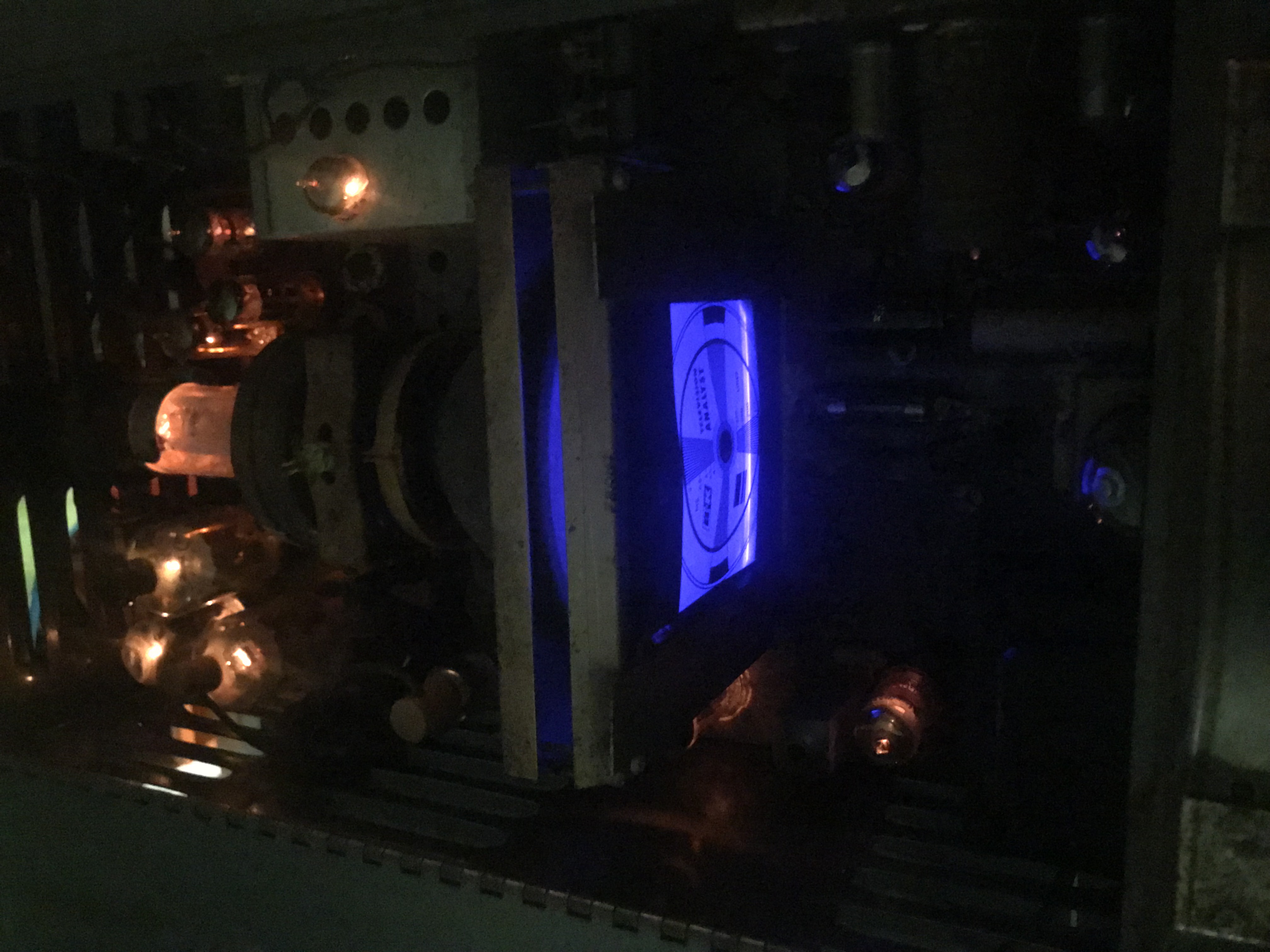
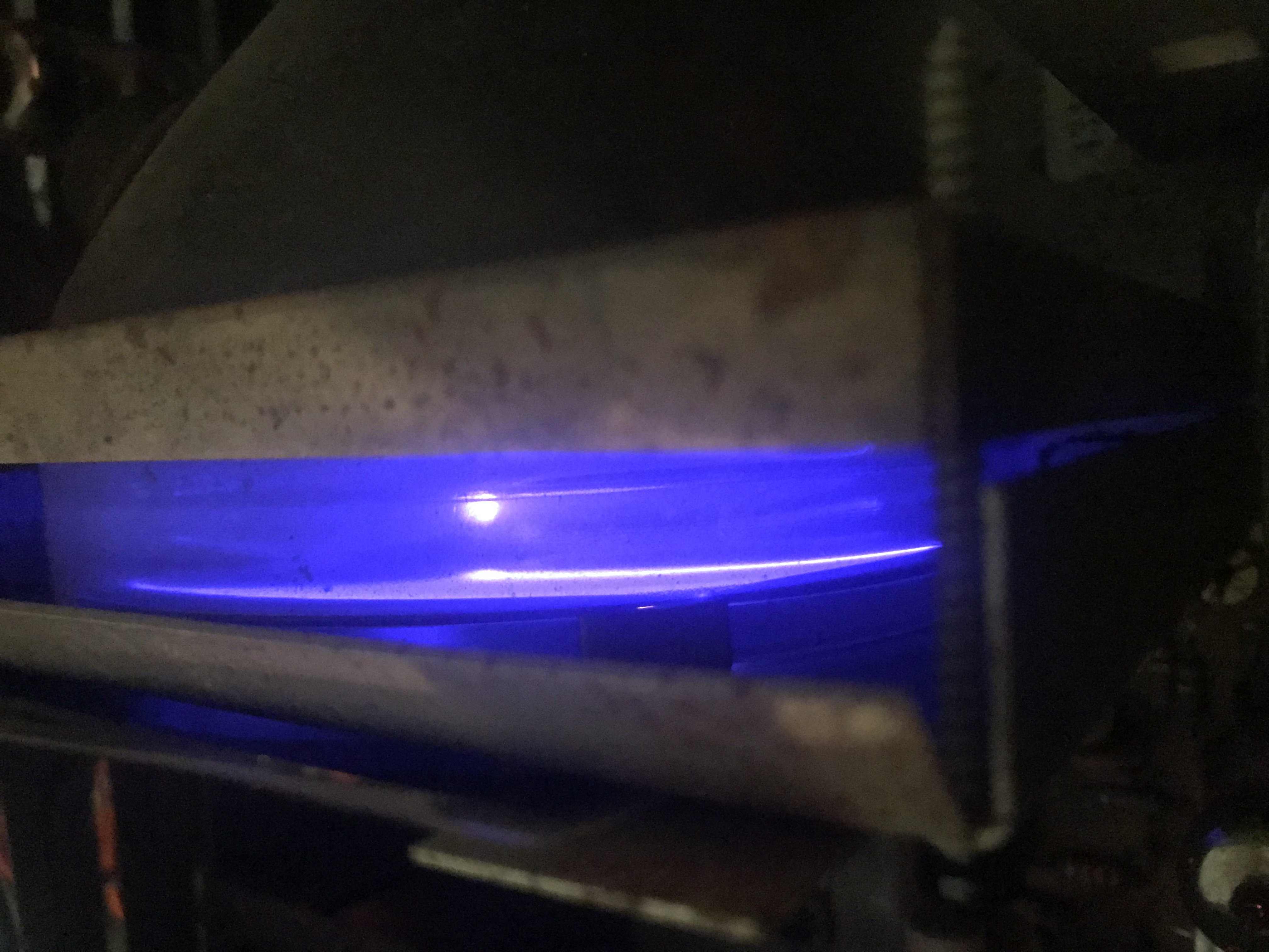
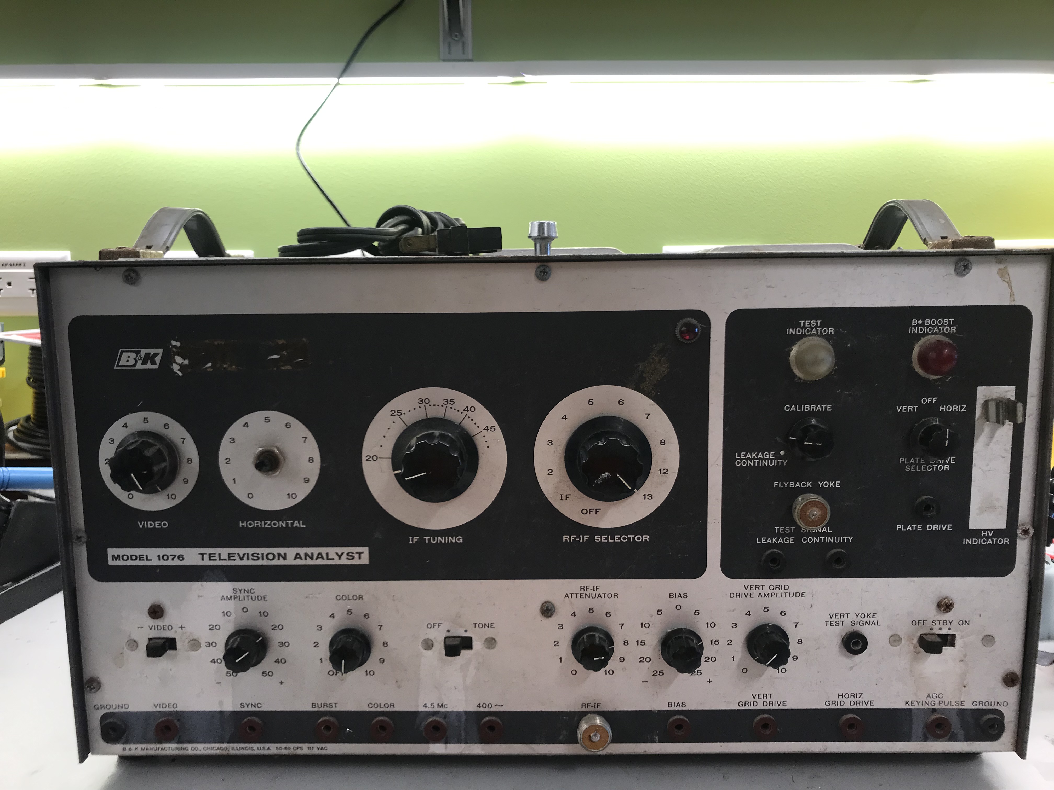
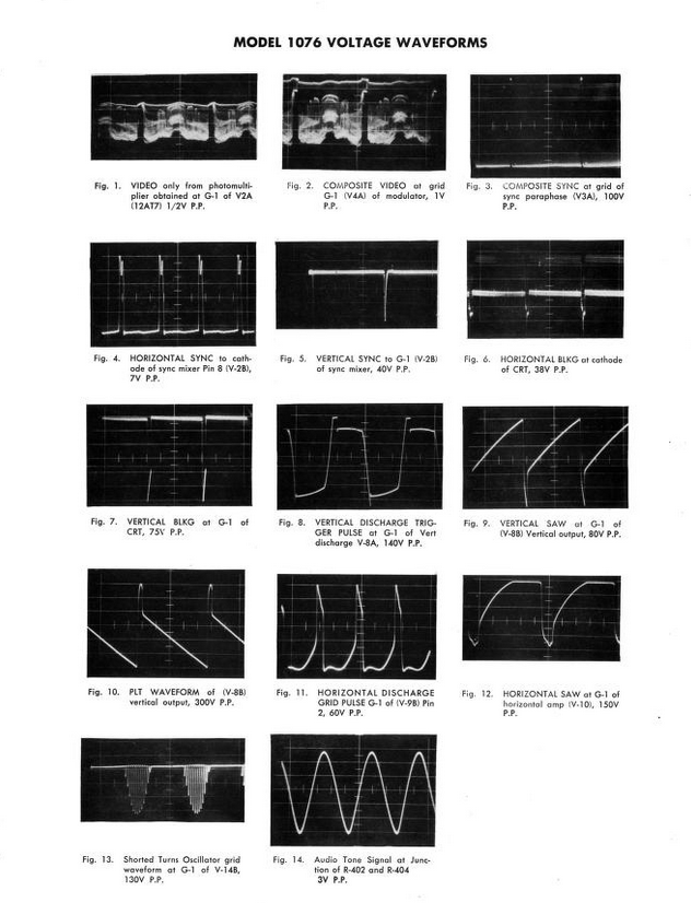
After yolk and ion trap adjustments, the CRT produced a decent raster. There are still horizontal frequency and linearity controls in need of adjustment. There were vertical sizing problems, but after letting the tubes heat up, the raster completely filled the CRT screen. I probed some of the taps on the front panel of the analyst (except the plate drive signals).
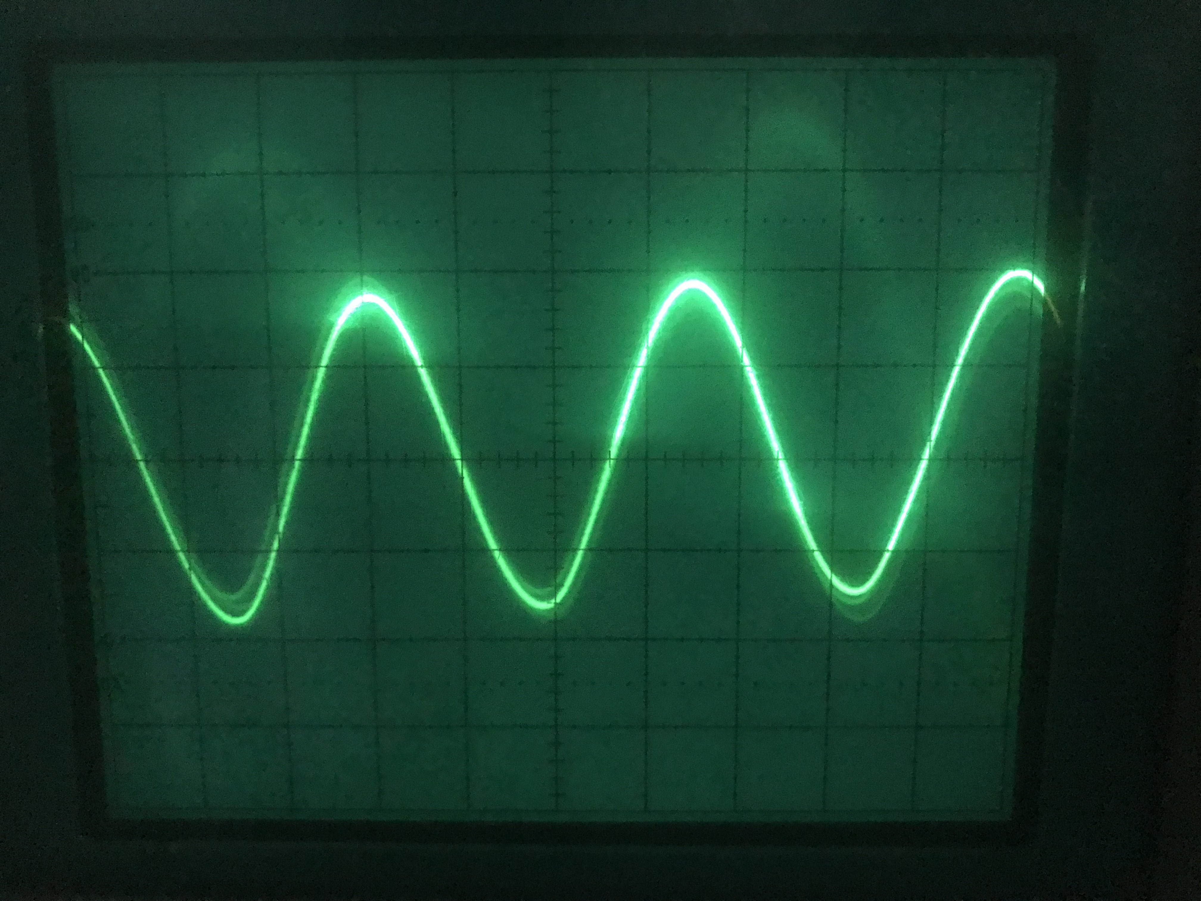
400Hz Audio Signal
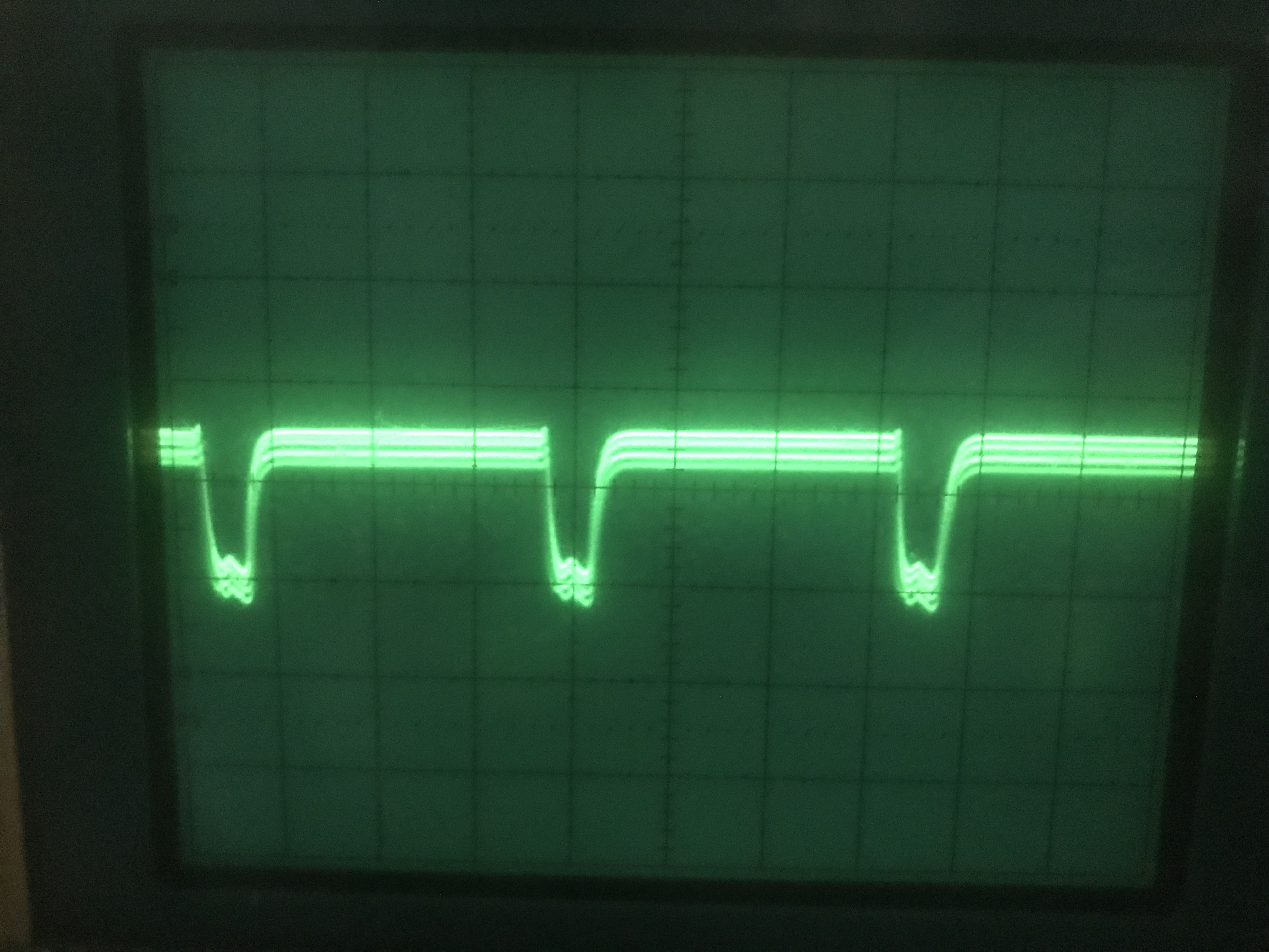
AGC Keying Pulse
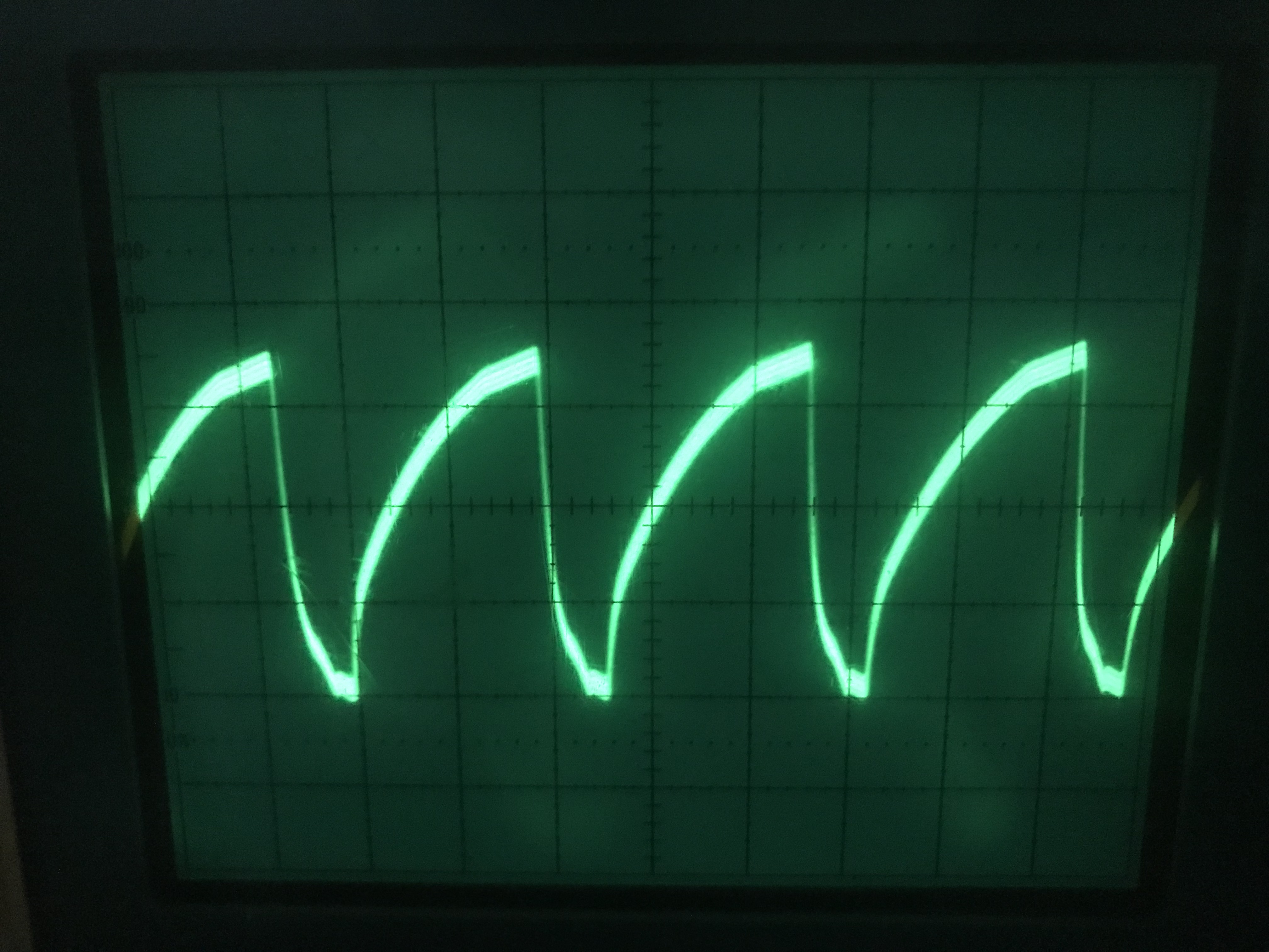
Horizontal Sweep Signal
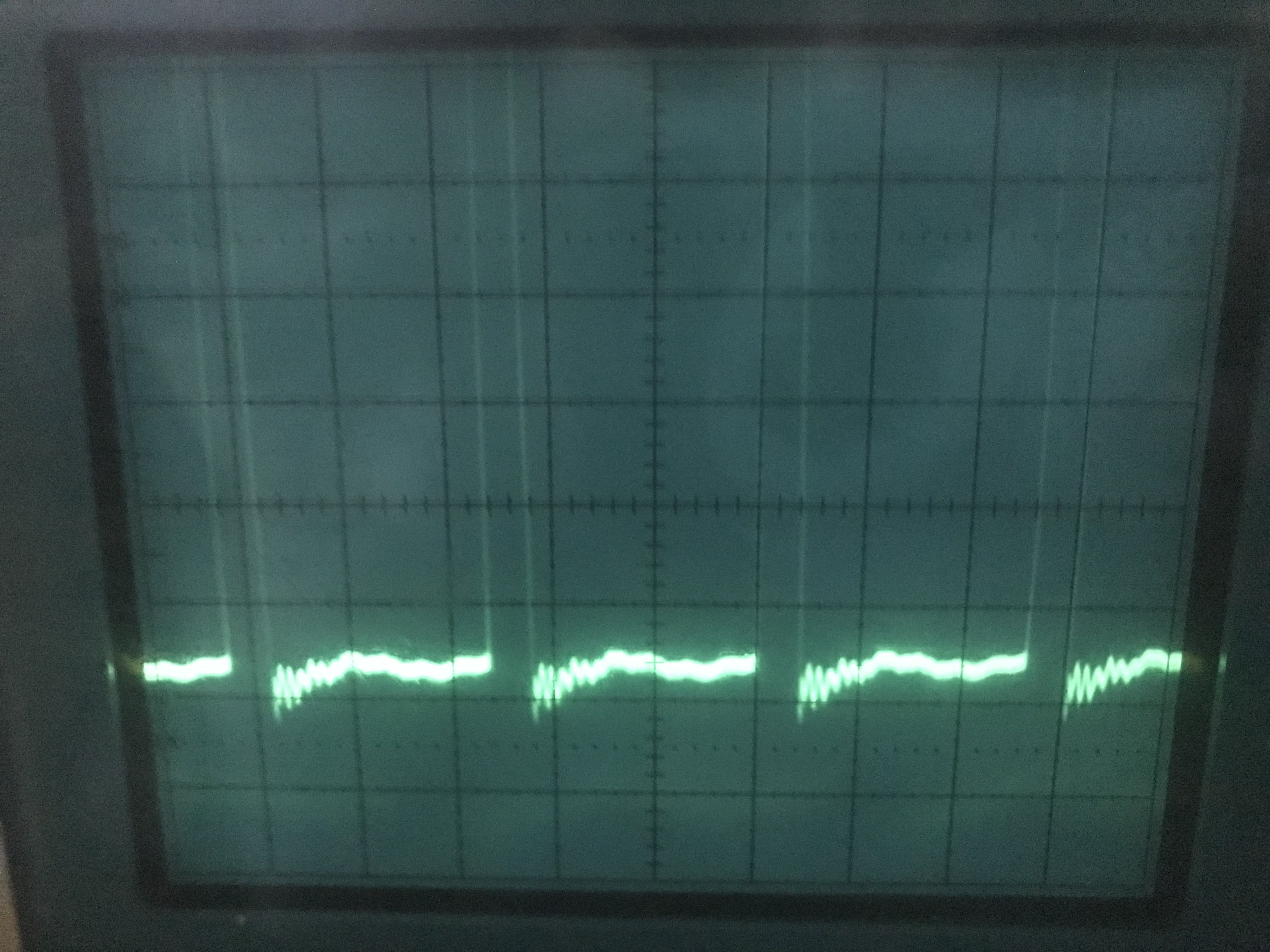
Synch Pulses
There is a special composite signal probe for this unit that I dont have. I am ordering it right now. Will update once I receive it so I can test a tube reciever.
